COVO TOOLING SYSTEM
LVD Press Brake Tooling
LVD-compatible press brake tooling for matched upper and lower tool setups.
Browse 95 COVO punches, dies and compatible tooling products for LVD press brake systems. Filter by product type, angle, height, material and die opening in the interactive catalog.
LVD tooling products
- LVD Punch 16.2 (16.2)
- LVD Punch 16.5 (16.5)
- LVD Punch 16.51 (16.51)
- LVD Punch 16.52 (16.52)
- LVD Punch 16.54 (16.54)
- LVD Punch 16.201 (16.201)
- LVD Punch 16.205 (16.205)
- LVD Punch 16.206 (16.206)
- LVD Die 26.211 (26.211)
- LVD Die 26.212 (26.212)
- LVD Die 26.213 (26.213)
- LVD Die 26.214 (26.214)
- LVD Die 26.215 (26.215)
- LVD Die 26.262 (26.262)
- LVD Die 26.263 (26.263)
- LVD Die 26.264 (26.264)
- LVD Die 26.265 (26.265)
- LVD Die 26.266 (26.266)
- LVD Punch 16.53 (16.53)
- LVD Punch 16.202 (16.202)
- LVD Punch 16.203 (16.203)
- LVD Punch 16.204 (16.204)
- LVD Die 26.216 (26.216)
- LVD Die 26.217 (26.217)
Selecting LVD-compatible press brake tooling
Start an LVD tooling replacement or custom-tool inquiry with the machine model and installed upper and lower clamping details. The catalog label is a starting point, not a guarantee that one profile fits every LVD machine.
- Share the existing tool reference and interface dimensions, plus photographs showing how the punch and die seat in their holders.
- Review punch and die working heights with the available stroke, open height, part geometry and any adapters already fitted to the machine.
- Define bend angle, inside radius, flange lengths, material and surface requirements. Confirm load limits and the first-piece measurement plan before production.
LVD-style tooling: review the assembled working height
Start an LVD-compatible tooling inquiry with the machine model, current upper and lower holders and an existing tool reference where available. Compare the full installed assembly rather than measuring a loose punch alone. Holders and adapters belong in the height and clearance review, together with the chosen punch and die. Record which surfaces establish seating and alignment, and attach a referenced drawing when a replacement must match an existing set. A catalog height or die opening is useful for selecting a candidate but does not prove that the tool can be installed in your particular configuration. For parts with return flanges, show intermediate bends as well as the final section so entry and withdrawal can be checked. State which dimensions and surfaces matter most in the first article. Where the existing tooling has wear or undocumented modifications, request an engineering review rather than copying its condition into a new specification.
Prepare the machine and part review
Punch, die and machine compatibility checklist
| Component | Evidence to provide | Selection decision |
|---|---|---|
| Upper punch | Tang and seating drawing, holder identity, retention features and loading direction. | Confirm the mounting first; then compare working angle, nose radius and return-flange clearance. |
| Lower die | Base and holder drawing, locating reference, V-opening, die angle and support arrangement. | Check mounting separately from the opening. Review the punch and die together for the actual part. |
| Holder or adapter | Model, assembly drawing, installed height and documented load and installation limits. | Identify every loaded interface. Do not treat a spacer or adapter as a dimension-only substitution. |
| Machine and part | Machine model, available opening, stroke, material grade, thickness, bend length and finished profile. | Review the complete envelope and job against documented component limits, then agree first-piece acceptance. |
Compare published specifications without filling the gaps
Open each candidate product to review its listed model, photographs and available specifications. Punch angle, nose radius and height describe different parts of the working geometry; a lower die's opening and mounting base are also different dimensions. A missing value is a question for the quotation, not permission to copy a number from a neighboring model. Keep the catalog reference and drawing revision in the inquiry so both parties are reviewing the same item. The selected examples below show actual catalog data and link to the full product records. They are comparison candidates, not a pre-approved matched tool set.
Define the part and the complete bend sequence
Provide a dimensioned finished section with material grade, thickness range, bend length, required angles and inside radii. Mark short flanges, return flanges, holes near bends and surfaces that must remain unmarked. Include the intended sequence or identify it as an open engineering question. A profile that appears suitable for one bend may still require a different setup for entry, subsequent bends or removal. Show the intermediate shapes when clearance is limited. This information lets the review distinguish a standard catalog candidate from a job that needs a special profile or a different process.
Keep load estimates separate from tooling approval
Use the bending-force calculator only for preliminary planning under its stated assumptions. Record the actual material data and bending method, and compare the job with the documented machine, tool, holder and loaded-section limits. Overall machine capacity is not a rating for an individual punch, die or adapter. Do not use a generic calculator result to approve a retention feature or an undocumented mounting arrangement. Resolve missing ratings and installation requirements before a controlled trial. The supplier's confirmed drawings and the machine manufacturer's instructions remain part of the setup record.
Agree the quotation and first-piece acceptance record
List the exact tool references, required lengths or segments, quantities and delivery destination. Separate confirmed requirements from open assumptions, and identify any existing tools that must be retained. Agree critical dimensions, angle and surface criteria and how the released part will be measured. Before production, match the received tooling to the approved record and follow the equipment manufacturer's installation and safe-working procedure. A successful sample does not replace interface or load documentation. Retain the accepted drawing revision and inspection result so a repeat order can refer to an agreed configuration rather than an unlabelled photograph.
Published catalog examples
Compare individual records; these examples are not a matched or approved tool set.
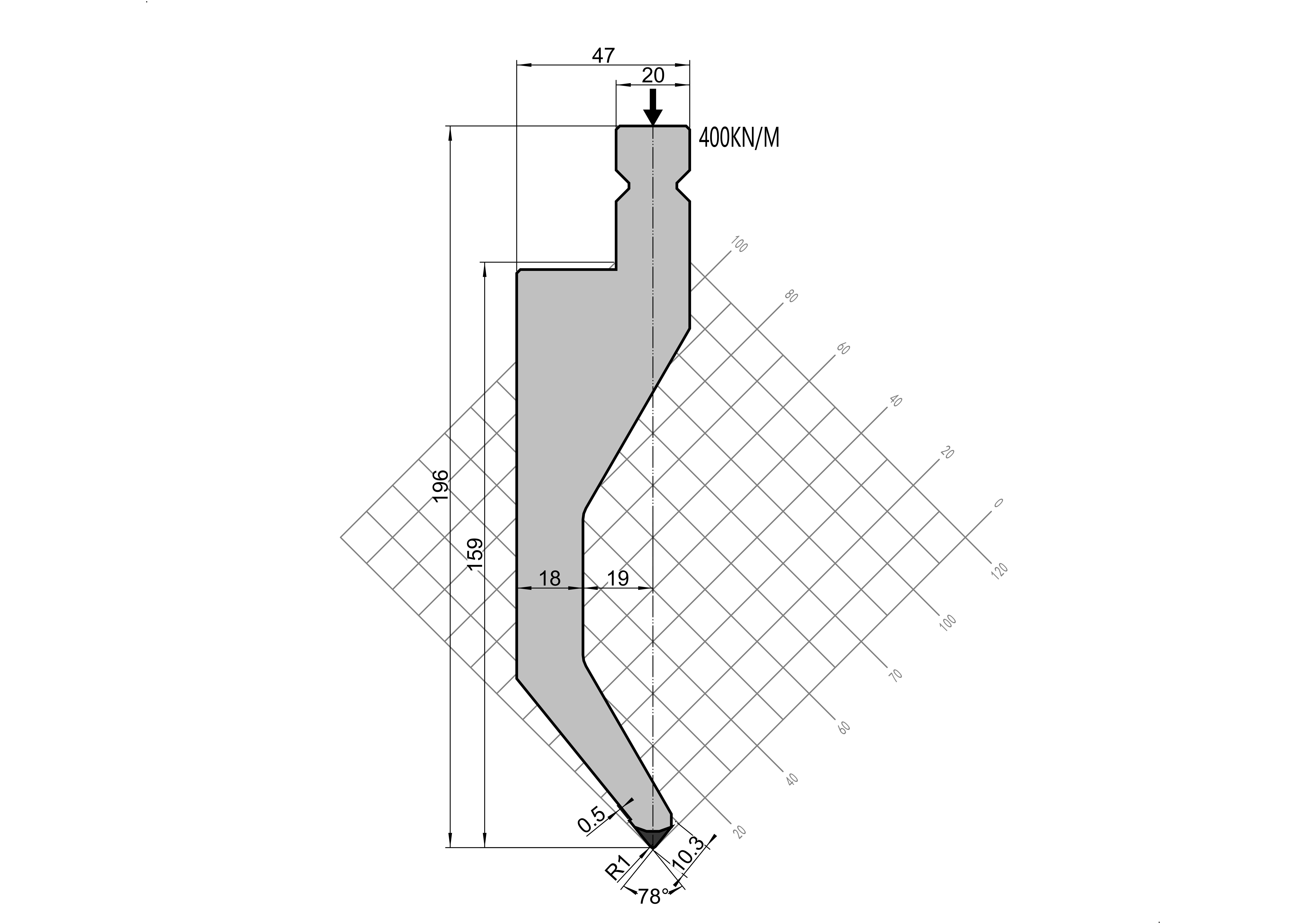
LVD Punch 16.2
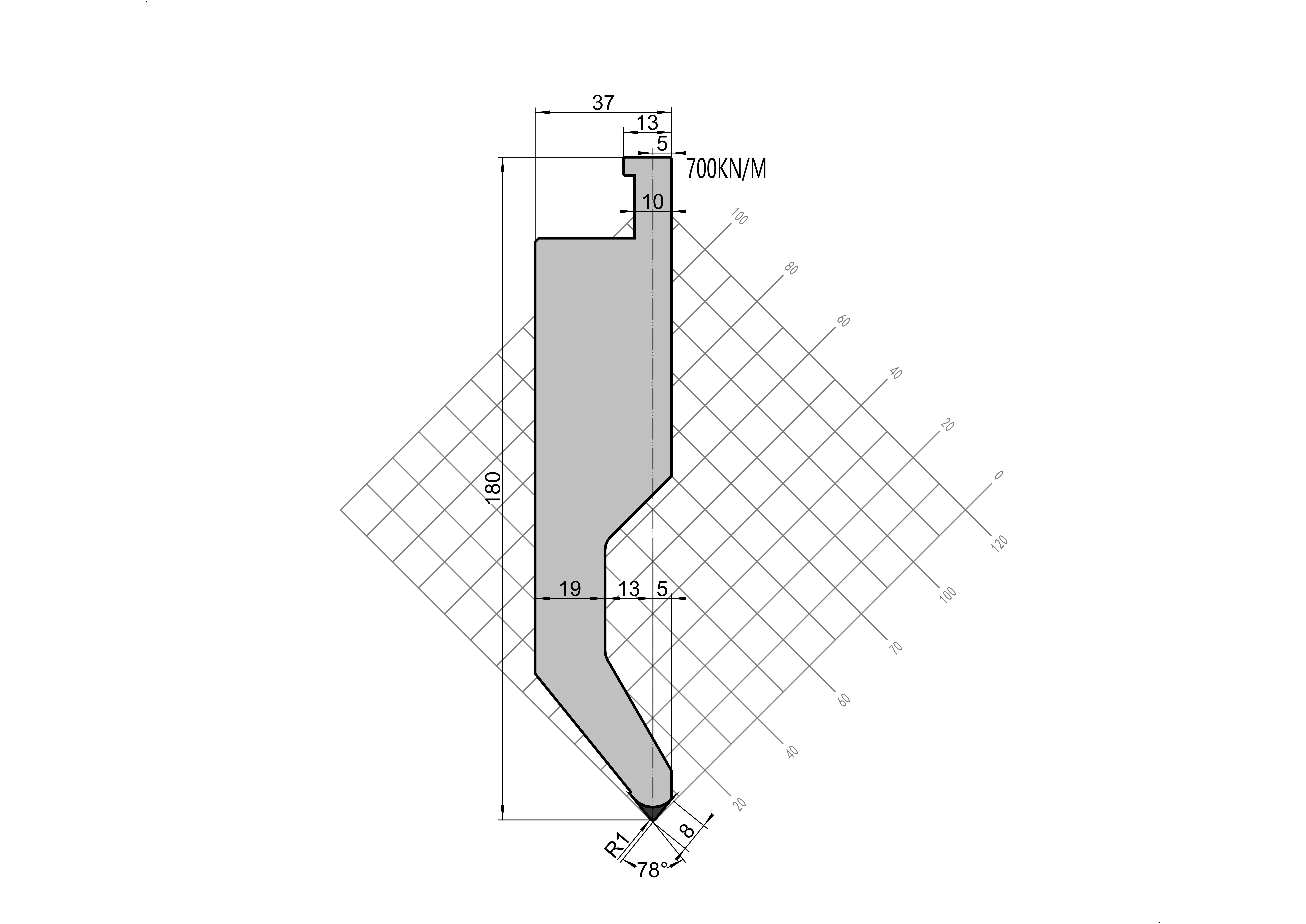
LVD Punch 16.5
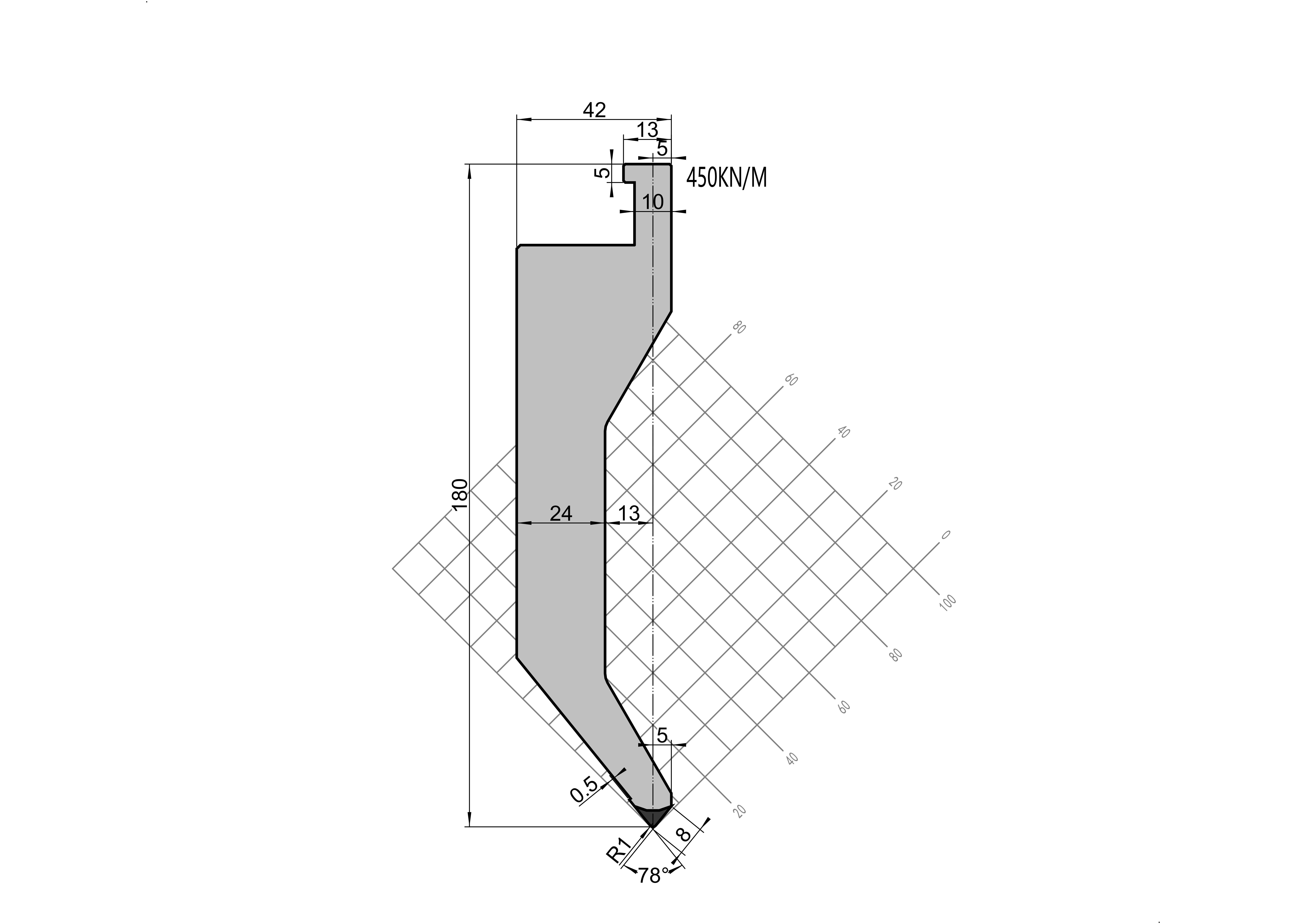
LVD Punch 16.51
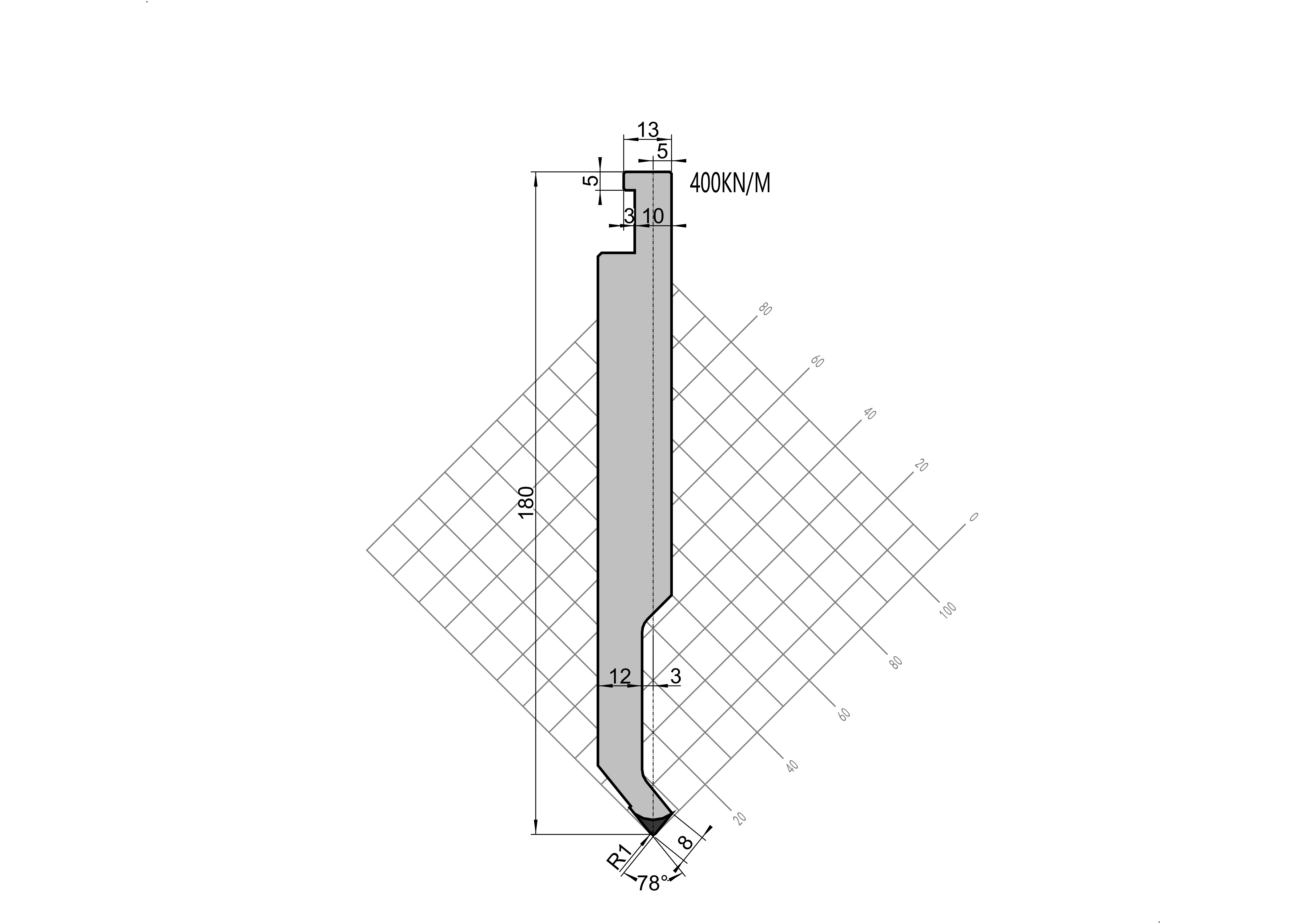
LVD Punch 16.52
Frequently asked questions
Will every tool here fit every LVD press brake?
No. This is a catalog family, not universal compatibility approval. Identify the installed upper and lower holders, compare referenced interface drawings and include any retrofit equipment. Ask for confirmation of the exact proposed assembly before ordering.
Can I select a replacement from the photograph alone?
A photograph helps identify a candidate, but it does not establish unshown dimensions, tolerances, seating references or load limits. Send the existing tool reference and a drawing where available, then resolve the missing information in the engineering review.
What if my part needs a non-standard tool?
Send the finished profile, material and machine information with the constraint that a standard tool cannot meet. COVO can review a custom tooling scope. Geometry, interfaces, limits and acceptance criteria need agreement before manufacture; custom does not mean universally compatible.
Brand names identify the requested interface or machine family; they do not imply OEM affiliation or universal compatibility. Confirm the installed system before ordering.
Prepare an engineering review · Estimate preliminary bending force · Explore custom forming tools
Specify the correct tooling
Provide the machine model, clamping interface, material, thickness, bend length and finished profile so COVO can verify compatibility and tooling clearance.
Browse all LVD products · Bending force calculator · Request a quote